
Pneumatic Cylinder
Filter
Filter
2 items
content loaded
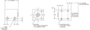
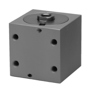
These are double acting air cylinders. Available in standard inch Bore size(s): 3/4" to 8" with forces up to 5030 lbs at 100 psi. This product has a 3/4" male thread.
Available in a variety of strokes. They are constructed of anodized aluminum and can be configured with single or double rod ends, a variety of mounting, duty styles, sensors and with a large catalog of accessories.
$161.79$170.50
Available for Purchase
Subject to factory lead times
Configure product to see pricing
These are double acting air cylinders. Available in standard inch Bore size(s): 3/4" to 8" with forces up to 5030 lbs at 100 psi. Available in a variety of strokes. They are constructed of anodized aluminum and can be configured with single or double rod ends, a variety of mounting, duty styles, sensors and with a large catalog of accessories.
Configure Product
Configure product to see pricing
These are double acting air cylinders. Available in standard inch Bore size(s): 3/4" to 8" with forces up to 5030 lbs at 100 psi. This product has a 3/4" male thread.
Available in a variety of strokes. They are constructed of anodized aluminum and can be configured with single or double rod ends, a variety of mounting, duty styles, sensors and with a large catalog of accessories.
$161.79$170.50
Available for Purchase
Subject to factory lead times
Configure product to see pricing
These are double acting air cylinders. Available in standard inch Bore size(s): 3/4" to 8" with forces up to 5030 lbs at 100 psi. Available in a variety of strokes. They are constructed of anodized aluminum and can be configured with single or double rod ends, a variety of mounting, duty styles, sensors and with a large catalog of accessories.
Configure Product
Configure product to see pricing
FAQS
- A pneumatic cylinder is a mechanical device that converts compressed air energy into linear (straight-line) motion and force. It consists of a cylindrical bore (barrel), a piston that seals and slides inside the bore, and a piston rod attached to the piston that extends through one end to connect to the external load. When compressed air is directed into the cylinder through a port on one side of the piston, the air pressure acts on the piston area to create a force that pushes the piston and rod in a straight line. The force produced equals the air pressure multiplied by the piston area. Pneumatic cylinders are the most common type of linear actuator in industrial automation because compressed air is available in virtually every manufacturing facility, they are simple, reliable, cost-effective, and easy to control with basic directional valves and PLCs.
- Pneumatic cylinders are available in many types to suit different applications. Round body cylinders are compact, lightweight general-purpose actuators. NFPA tie-rod cylinders are heavy-duty, standardized, interchangeable, and rebuildable. Compact and short-stroke cylinders are space-saving designs for tight installations. Guided cylinders incorporate guide rods for non-rotating, side-load-resistant motion. Rodless cylinders provide long-stroke motion without a protruding rod. Pancake cylinders provide ultra-low-profile actuation. Specialty cylinders include sine, locking, tandem, and multi-position designs. Each type is optimized for specific force, stroke, space, precision, and environmental requirements. Centro carries a comprehensive selection including Compact Automation, Fabco-Air, and other leading pneumatic cylinder brands to cover virtually any industrial application.
- The theoretical force output of a pneumatic cylinder is calculated by multiplying the air supply pressure by the effective piston area. For the extend (push) stroke: Force = Pressure × Piston Area, where Piston Area = π × (Bore Diameter/2)². For the retract (pull) stroke of a single-rod cylinder, the rod reduces the effective area: Force = Pressure × (Piston Area – Rod Area). For example, a 2-inch bore cylinder at 100 PSI: Piston Area = π × 1² = 3.14 square inches. Extend force = 100 × 3.14 = 314 pounds. The actual usable force is less than the theoretical force because of internal friction from seals and bearings (typically 5-15% of theoretical force) and because some force may be needed to overcome backpressure on the exhaust side. Always apply a safety factor of 25-50% above the calculated required force when selecting a cylinder size.
- Pneumatic cylinder speed is determined by several interrelated factors. Air flow rate to and from the cylinder — the volume of air that can enter and exit the cylinder per unit time, controlled by the valve size, tubing size, fitting size, and flow control valves in the circuit. Larger valves, tubing, and fittings allow more flow and faster speed. Cylinder bore size — larger bore cylinders require more air volume to fill, so they move slower at the same flow rate. Load — heavier loads require more force to accelerate and decelerate, reducing speed and increasing settling time. Operating pressure — higher pressure provides more driving force for faster acceleration but also requires more flow to fill the cylinder volume. Cushioning — internal or external cushioning slows the cylinder at end of stroke, reducing impact but adding to the total cycle time. Friction — seal friction, rod bearing friction, and external load friction all resist motion. Flow control valves (meter-out type) are the standard method for adjusting cylinder speed to the desired rate for the application.
- Start by identifying the symptom. Cylinder does not move at all — check that air supply is connected and at the correct pressure, verify the directional valve is shifting (listen for a click or check the indicator), check that air lines are connected to the correct ports, and verify there is no mechanical obstruction or load jam. Cylinder moves slowly — check air supply pressure (low pressure reduces force and speed), check for restrictions in the air lines (kinked tubing, clogged filters, undersized fittings), verify flow control valves are open sufficiently, and check for internal leakage past worn piston seals reducing effective pressure. Cylinder does not hold position under load — check for leaking piston seals (apply soapy water to exhaust port while pressurized and stationary; bubbles indicate bypassing), check directional valve for internal leakage, and verify the cylinder is receiving sustained pressure (not being exhausted by the valve). Cylinder drifts or creeps — indicates seal wear or valve leakage. Erratic motion — check for moisture in the air supply, inconsistent pressure, or mechanical binding in the load mechanism.