
Valve Systems
Valve systems tailored for pneumatics play a crucial role in orchestrating the controlled movement of pneumatic actuators within diverse industrial applications. These systems are designed to manage compressed air ...
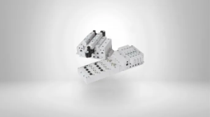
Valves and bases are integral components of pneumatic systems, playing a pivotal role in controlling compressed air flow to achieve specific automation tasks. Valves act as switches, regulating the air supply to pneumatic actuators, which move mechanical components in response to signals. Bases, also known as manifolds, provide a centralized platform for mounting and connecting multiple valves, streamlining the assembly and maintenance of pneumatic circuits. These components are crucial for achieving precise and efficient motion control in various industrial and automation applications. Whether it's a simple on-off operation or more complex proportional control, selecting appropriate valves and bases is paramount to optimizing the performance of pneumatic systems and enhancing overall productivity.
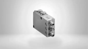
A Communication and Control Module (CCM) is a fundamental component in modern technological systems that enables seamless communication and coordination between various interconnected devices or subsystems. These modules are engineered to facilitate data exchange, monitor system status, and manage processes efficiently. They serve as the nerve center of complex systems, such as industrial automation, smart homes, and automotive control systems. CCMs have sophisticated hardware and software, including microcontrollers, sensors, and communication protocols, to ensure reliable data transmission and decision-making capabilities. Whether it's coordinating the functioning of interconnected IoT devices, managing data flow in a network, or overseeing critical processes in a manufacturing plant, a Communication and Control Module plays a pivotal role in ensuring connectivity, real-time monitoring, and responsive control, thus driving the efficiency and effectiveness of modern technological ecosystems.
$185.85
Subject to factory lead times
$185.85
Subject to factory lead times
$185.85
Subject to factory lead times
$185.85
Subject to factory lead times
$140.78
Subject to factory lead times
$140.78
Subject to factory lead times
$132.74
Subject to factory lead times
$201.97
Subject to factory lead times
$201.97
Subject to factory lead times
$129.20
Subject to factory lead times
Subject to factory lead times
Subject to factory lead times
$185.85
Subject to factory lead times
$185.85
Subject to factory lead times
$185.85
Subject to factory lead times
$185.85
Subject to factory lead times
$140.78
Subject to factory lead times
$140.78
Subject to factory lead times
$132.74
Subject to factory lead times
$201.97
Subject to factory lead times
$201.97
Subject to factory lead times
$129.20
Subject to factory lead times
Subject to factory lead times
Subject to factory lead times
- A valve manifold (also called a valve island or valve terminal) is an integrated assembly that mounts multiple directional control valves on a common base with shared air supply and exhaust ports. Instead of piping air supply and exhaust lines to each individual valve separately, the manifold distributes supply air internally and collects exhaust centrally, dramatically reducing the amount of tubing, fittings, and mounting hardware required. Valve manifolds also integrate electrical connections through a single multi-pin connector or fieldbus node, simplifying wiring back to the PLC. The main advantages over individual valves are reduced installation time and cost, less tubing and fewer leak points, centralized maintenance, smaller footprint, and cleaner machine design. They are the standard approach for machines that control multiple cylinders, grippers, or actuators from a single location.
- Modern pneumatic valve systems offer a range of communication options to connect with PLCs and controllers. At the basic level, individual solenoid valves are wired point-to-point with discrete I/O — each valve gets its own output from the PLC. Multi-pin connectors consolidate all valve wiring into a single cable with a D-sub or multi-pole connector, reducing cable runs. For larger systems, fieldbus and industrial Ethernet protocols are the standard — valve islands with integrated fieldbus nodes communicate over EtherNet/IP, PROFINET, PROFIBUS, DeviceNet, or IO-Link, allowing a single network cable to control dozens of valves while also providing diagnostic feedback such as coil status, short-circuit detection, and supply pressure monitoring. Fieldbus-connected valve systems reduce wiring cost and installation time significantly and are the preferred approach for any system with more than a handful of valves.
- The designation describes the number of ports and the number of switching positions. A 3/2-way valve has three ports (pressure in, cylinder port, exhaust) and two positions — it is used to control single-acting cylinders (spring return), blow-off applications, or vacuum circuits where air needs to flow in one direction and exhaust when de-energized. A 5/2-way valve has five ports (pressure in, two cylinder ports, two exhaust ports) and two positions — it is used to control double-acting cylinders, directing air to one side of the piston while exhausting the other. If your actuator is double-acting (most industrial cylinders are), you need a 5/2-way or 5/3-way valve. If the actuator is single-acting or the application only requires on/off air flow in one direction, a 3/2-way valve is sufficient.
- The correct valve size is primarily determined by the flow rate required by the actuators it controls. Larger cylinders moving at higher speeds consume more air per cycle and require valves with higher flow capacity, typically expressed as Cv (flow coefficient) or standard liters per minute. Undersized valves restrict airflow, causing the cylinder to move slower than intended and reducing machine cycle rates. To size correctly, calculate the air volume consumed per stroke of each cylinder (based on bore size, stroke length, and operating pressure), multiply by the required cycle rate, and select a valve with a Cv that comfortably exceeds that demand. Also consider the manifold's total flow capacity if multiple valves will operate simultaneously. Other factors include operating pressure range, port thread size (M5, 1/8", 1/4", 1/2"), response time requirements, and available mounting space.
- Yes, modularity is one of the key advantages of manifold-based valve systems. Most manufacturers design their valve islands so that additional valve stations can be added to the manifold by attaching extension modules and blanking plates. When specifying the initial system, it is good practice to include spare stations (capped with blanking plates) to accommodate future expansion without disassembling or replacing the manifold. For fieldbus-connected systems, adding valve stations may require updating the PLC I/O configuration to recognize the additional outputs, but the network cabling typically does not change. If the expansion exceeds the capacity of the existing manifold's air supply or the fieldbus node's I/O count, a second manifold assembly can be added on the same network segment.