
Instrumentation, Measurement and Control - Madison
Instrumentation refers to devices that measure or control physical variables such as temperature, level, flow, or pressure. These products are essential in the industry because they allow for maximum output with mi...
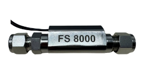
Float switches are one of the simplest and most dependable ways to sense liquid level. A buoyant float rises and falls with the liquid and opens or closes a switch at a set point to start a pump, stop a fill or trigger a high or low level alarm.
Float Switch Types
- Tethered cable floats – wide switching range for sumps and wastewater
- Vertical stem floats – compact, precise point level in tanks
- Side-mount floats – install through the tank wall
- Multi-point float switches – several level points on one stem
- Sanitary and chemical-resistant floats – stainless, PVDF and polypropylene
Choosing a Float Switch
Consider the liquid's specific gravity, temperature and chemical makeup, along with the tank's size and mounting options. Check the switch rating against the load. Many pumps need a relay or motor control panel. Avoid using floats in turbulent or heavily coated liquids unless they're designed for it.
Centro offers float switches for water, wastewater, chemical and process tanks, and can help you match material and mounting to your application.
Related categories: Liquid Level | Level Transmitters | Float Switch | Radar | Differential Pressure Control

Liquid level switches detect when a liquid reaches a set point in tanks, sumps and vessels. They control pumps and valves and trigger high and low alarms.
Level Switch Types
- Float switches – simple, reliable switching
- Vibrating fork switches – unaffected by foam or turbulence
- Conductivity switches – conductive liquids
- Optical switches – compact point detection
- Capacitive switches – liquids and slurries
Choosing a Switch
Consider liquid type, temperature, pressure, buildup and mounting. Use an independent high-level switch for overfill protection.
Centro supplies liquid level switches for tanks and sumps.
Related categories: Liquid Level | Level Sensors | Differential Pressure Control | Water Gauges | Radar

Panel meters and displays turn signals from transmitters, sensors and electrical circuits into clear readings on a control panel. Operators can see flow, temperature, pressure, level, speed or current at a glance, and many models also provide alarms and retransmitted outputs.
Display Options
- Process meters – read 4-20 mA and 0-10 V signals in engineering units
- Electrical meters – AC/DC voltage, current and power
- Temperature displays – direct thermocouple and RTD inputs
- Rate and totalizer meters – flow rate, totals and counts from pulse inputs
- Large-digit displays – visible across the plant floor
Choosing a Meter
Match the input type and range, then decide whether you need relay alarms, analog retransmission or serial communication. Check the panel cutout size (1/8 DIN is common), power supply and front-panel rating for washdown areas. Loop-powered meters are useful where no separate power is available.
Centro carries panel meters and displays from leading instrumentation brands and can help you match one to your signal.
Related categories: Controllers | PID

Liquid level sensors detect or measure liquid in tanks and containers. They support pump control, inventory tracking and overfill protection.
Sensor Types
- Ultrasonic sensors – non-contact continuous level
- Capacitive sensors – point and continuous level
- Optical sensors – compact point detection
- Submersible pressure sensors – hydrostatic level
- Float sensors – simple, dependable
Choosing a Sensor
Consider liquid type, tank size, mounting and the output you need. Foam, vapor and buildup affect some technologies.
Centro supplies liquid level sensors.
Related categories: Liquid Level | Water Gauges | Level Switches | Differential Pressure Control | Radar
Flow switches monitor liquid or air flow and trigger alarms or shutdowns when flow is too low or too high. They protect pumps, heat exchangers, chillers and cooling systems.
Flow Switch Types
- Paddle flow switches – simple, rugged
- Thermal flow switches – no moving parts
- Piston and magnetic flow switches – precise set points
- Air flow switches – ducts and HVAC
Choosing a Switch
Select by media, flow range, pipe size, pressure and temperature. Adjustable set points add flexibility.
Centro supplies flow switches.
Related categories: Flow Control | Flow Transmitters | Flow Meters | Flow Sensors | Flow Control Accessories
Configure product to see pricing
Configure product to see pricing

$517.33$649.00
$656.03$823.00
$710.23$891.00
$167.40$210.00
Subject to factory lead times
$334.79$420.00
Subject to factory lead times

$148.27$186.00

$38.27$48.00

$361.10$453.00
$167.40$210.00
Subject to factory lead times

$598.64$751.00

$271.82$341.00
Subject to factory lead times

$271.82$341.00
Subject to factory lead times

$543.64$682.00
Subject to factory lead times

$403.35$506.00

$94.86$119.00
Subject to factory lead times

$94.86$119.00
Subject to factory lead times

$189.72$238.00
Subject to factory lead times

$121.96$153.00
Subject to factory lead times
Subject to factory lead times

Subject to factory lead times

Subject to factory lead times

Subject to factory lead times

$0.00$273.00
Configure product to see pricing
Configure product to see pricing
$517.33$649.00
$656.03$823.00
$710.23$891.00
$167.40$210.00
Subject to factory lead times
$334.79$420.00
Subject to factory lead times
$148.27$186.00
$38.27$48.00
$361.10$453.00
$167.40$210.00
Subject to factory lead times
$598.64$751.00
$271.82$341.00
Subject to factory lead times
$271.82$341.00
Subject to factory lead times
$543.64$682.00
Subject to factory lead times
$403.35$506.00
$94.86$119.00
Subject to factory lead times
$94.86$119.00
Subject to factory lead times
$189.72$238.00
Subject to factory lead times
$121.96$153.00
Subject to factory lead times
Subject to factory lead times
Subject to factory lead times
Subject to factory lead times
Subject to factory lead times
$0.00$273.00
- Selecting the right process instrument starts with defining four things: what variable you need to measure (temperature, pressure, flow, or level), the process conditions the instrument will face (media type, temperature range, pressure range, corrosiveness, and whether the environment is hazardous), the accuracy and response time your application requires, and how the measurement data needs to be communicated (local display only, 4–20 mA signal to a PLC/DCS, or digital protocol like HART or Modbus). For temperature, the choice between thermocouples, RTDs, and infrared sensors depends on the temperature range and accuracy needed. For pressure, gauge type, range, wetted materials, and whether you need local indication or a remote transmitter signal are the key decisions. For flow, the fluid properties (conductive liquid, gas, steam, slurry) determine whether a magnetic, ultrasonic, Coriolis, vortex, or variable-area meter is the best fit. For level, vessel conditions (open vs. pressurized, clean liquid vs. foam/solids) guide the choice between float switches, ultrasonic, radar, or differential pressure technologies. Centro's instrumentation specialists can help you match the right technology to your specific process conditions and budget.
- Accurate process instrumentation is the foundation of safe, efficient, and compliant operations. Every control loop — whether it manages boiler pressure, reactor temperature, tank level, or pipeline flow — depends on instruments that provide reliable, real-time measurements. If a temperature sensor reads inaccurately, a heater may overshoot and damage the product or create a safety hazard. If a level transmitter drifts, a tank may overflow or run dry. If a flow meter is undersized, the control system cannot maintain the correct feed rate. Beyond safety and quality, accurate instrumentation directly impacts energy consumption, raw material usage, and regulatory compliance. Calibrated, properly specified instruments reduce waste, prevent unplanned shutdowns, and provide the data required for regulatory reporting and quality documentation.
- A process control loop is a system that continuously measures a process variable, compares it to a desired setpoint, and adjusts an output to keep the variable at the setpoint. The loop consists of three elements: the sensor/transmitter (measures the variable — e.g., a thermocouple measuring temperature), the controller (compares the measurement to the setpoint and calculates a corrective output — typically a PID controller), and the final control element (adjusts the process — e.g., a control valve that opens or closes to change steam flow). Instruments are the eyes and ears of the loop — without accurate, responsive sensors and transmitters, the controller cannot make correct decisions, and the process drifts out of specification. The entire loop must be properly engineered as a system — sensor accuracy, transmitter range, controller tuning, and valve sizing must all be matched to the process requirements.
- Industrial instruments communicate with controllers and PLCs using standardized electrical signals. The 4–20 mA analog current loop is the most widely used signal in process instrumentation — it transmits a variable measurement as a proportional current (4 mA = zero/low range, 20 mA = full scale), and the current-based signal is resistant to voltage drop and electrical noise over long cable runs. The 0–10 V DC voltage signal is used in some HVAC and building automation applications but is more susceptible to noise and cable length limitations. Discrete (on/off) signals — from switches, relays, and transmitter alarm contacts — indicate threshold conditions like high level, low pressure, or flow/no-flow. Digital communication protocols — HART (layered on top of 4–20 mA for configuration and diagnostics), Foundation Fieldbus, PROFIBUS PA, and IO-Link — enable bidirectional communication between the instrument and the control system for advanced diagnostics, remote configuration, and multi-variable data.
- When instruments are installed in locations classified as hazardous (areas where flammable gases, vapors, or combustible dusts may be present), they must be approved for that classification to prevent ignition. Key considerations include the area classification (Class I for gases/vapors, Class II for dusts, with Division 1 for normally present hazards and Division 2 for abnormal conditions — or Zone 0/1/2 under ATEX/IECEx), the protection method (intrinsic safety, explosion-proof, non-incendive, or purged/pressurized), and the specific gas group and temperature class. Intrinsically safe (IS) instruments — used with IS barriers in the safe area — limit energy to levels too low to cause ignition and are the most common and practical approach for low-power sensors and transmitters. Explosion-proof enclosures contain any internal explosion and are used for higher-power devices. Always verify the instrument's certification (FM, CSA, ATEX, IECEx) matches the area classification before installation.